Free shipping from 1 999 Kč
Fast shipping
Verified store
Thousands of customers




Free shipping from 1 999 Kč
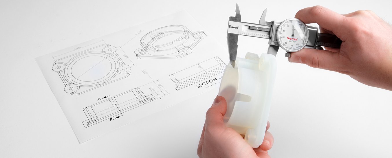
A well-prepared 3D model saves time, material and money. For a decorative item, it is often enough for the file to open in the slicer. With a functional part, however, scale, the correct format, wall thicknesses, clearances between parts and whether the model is actually printable all matter.
This guide summarizes what to check before sending files for 3D printing or before slicing at home. It is suitable for technical parts, covers, brackets, replacement components, prototypes and small batches.
Before exporting or placing an order, check the following in particular:
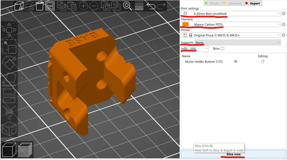
STL is the most common format for 3D printing. It describes the model's surface as a mesh of triangles. It is simple, supported by practically all slicers and fully sufficient for many jobs.
However, it has limitations. STL does not store units, colors, materials or the model history. If a model is exported in inches and the slicer loads it as millimeters, the part may be 25.4 times smaller. That is why it is important to check at least one known dimension after importing.
STL is suitable when:
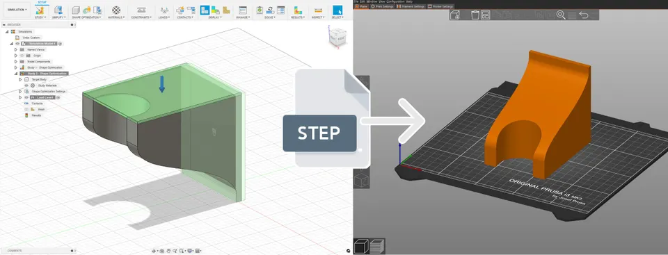
STEP is a CAD format for more precise exchange of technical models. It is not a triangular mesh, but a description of solid geometry. This makes it easier to modify, measure and check.
For functional components, STEP is often more valuable than STL alone. If a hole needs to be adjusted, a wall thickness changed, a chamfer added or an assembly checked, working from a STEP file is significantly easier. Modern slicers can often open STEP files directly, but the model is still converted into a printable mesh when preparing the print.
Send STEP especially when:
The best practice for custom printing is simple: send STEP as the source technical model and STL as a preview of how you intended the export for printing to look.
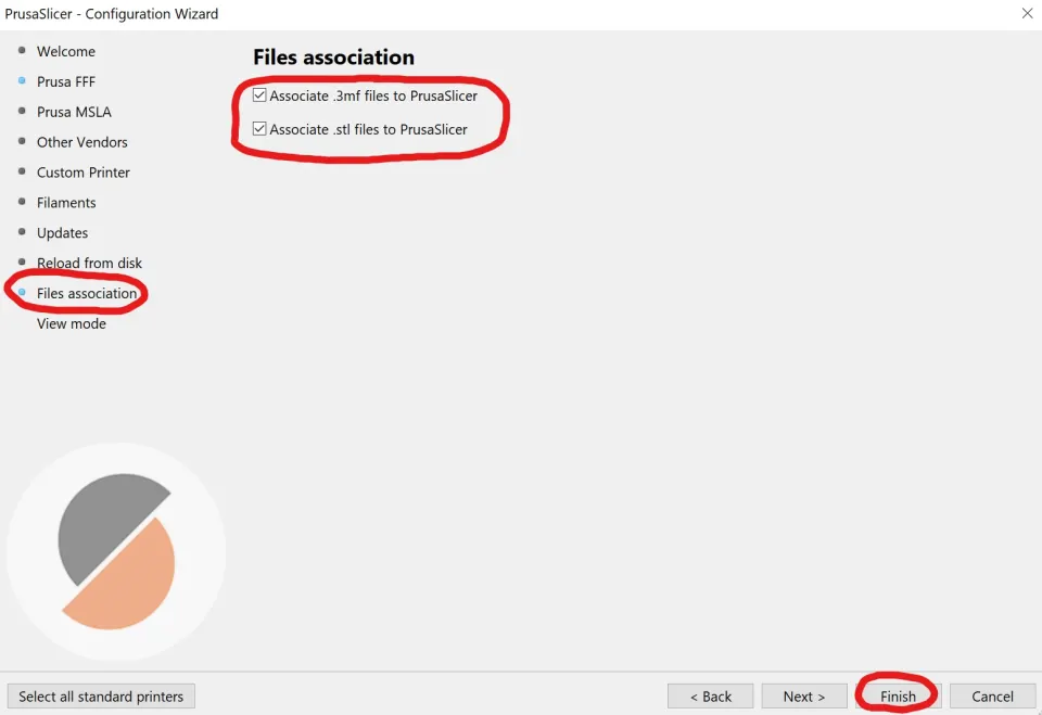
3MF is useful when you want to transfer more than just the shape. It can contain information about multiple objects, their positions, colors, materials and sometimes slicer settings. It is practical for multi-material printing, pre-prepared projects and models with multiple parts on one build plate.
For a standard order of a technical part, however, it does not replace STEP. If someone needs to check or modify the part in CAD, still send STEP as well.
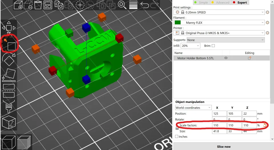
In practice, 3D printing is prepared in millimeters. Even if you model in centimeters or inches, set the export for printing to millimeters and check the dimensions after importing.
Practical procedure:
If the model is the wrong size, do not correct a functional part by estimating percentages in the slicer. Return to CAD, set the units correctly and export again. Scaling in the slicer makes sense for decorations, figurines or models. With parts containing holes, threads and mating surfaces, it can change clearances and ruin the function.
Tolerance indicates how large a deviation from the designed dimension is still acceptable. Clearance is an intentional gap between two parts so that they can fit together, slide or rotate.
Example: if you design a 10.00 mm pin and a 10.00 mm hole, this is not a good design for standard 3D printing. Even if the print is very accurate, the surface will not be perfectly smooth and the hole is often slightly smaller. To insert the pin, you need to enlarge the hole or reduce the pin size.
Approximate starting values for plastic parts:
| Use | Recommended initial clearance |
|---|---|
| Tight fit after fine-tuning | 0.1 to 0.2 mm |
| Standard insertion for FDM printing | 0.3 to 0.5 mm |
| Looser sliding fit or hinge for FDM | 0.5 to 0.8 mm |
| Finer resin printing | 0.1 to 0.3 mm |
| Larger parts or longer contact surfaces | add allowance according to the contact length |
Treat these as a starting point, not a universal standard. The material, print orientation, printer calibration, part size and post-processing can all change the result. For a batch or a more expensive part, it is worthwhile to first print a small test sample with several clearances.
If a lid needs to fit onto an FDM-printed box, do not start with zero clearance. For a simple fit, try approximately 0.3 mm on each side, for example. This may be just right for a small lid, while a larger cover may require more due to corner deformation.
For a pin with a diameter of 10 mm, design the hole according to the desired behavior. For a tighter hand fit, a hole of 10.2 to 10.3 mm may make sense. For free rotation, 10.5 mm or more may be better. With holes after FDM printing, expect the inner diameter to turn out smaller than in the model.
With a self-tapping screw, do not print a final metric thread without careful consideration. It is often better to design a pilot hole, test the diameter on a sample and possibly use a threaded insert. For repeated screwing, heat-set brass inserts are more reliable than a plastic thread.
With ible latches, consider the direction of the layers. The part is weaker between layers than within the layer plane, so a thin tab oriented in the wrong direction can break. Add a radius at the root of the latch, avoid sharp internal corners and plan for a prototype.
The model must have volume. A surface without thickness, such as a shell from a visualization program, is not a printable part by itself. Every wall must be thick enough for the printer to create it.
For standard FDM printing with a 0.4 mm nozzle, it is sensible to design walls as multiples of the extrusion width. Instead of a 0.55 mm wall, 0.8 mm, 1.2 mm or 1.6 mm is more practical. For sturdy brackets, it is often better to start at around 2 to 3 mm, depending on the load and geometry.
With fine lettering, grooves and reliefs, remember that the slicer cannot print details smaller than the nozzle, material and layer height allow. What looks good on a monitor may disappear or merge in the print.
The slicer needs to know what is inside and what is outside. Therefore, the model should be closed, solid and free of mesh errors.
Check in particular:
With CAD models, it is best to fix the problem in the source rather than in the STL. Automatic mesh repair can help, but with a technical part it can also change the dimensions or remove a detail that was meant to be functional.
When exporting STL, you usually set the fineness of the triangular mesh. Different programs use different names, such as chord height, deviation, angle tolerance, refinement or resolution.
An overly coarse export turns a cylinder into a visibly polygonal shape. An overly fine export creates a huge file that opens slowly, while the print itself may not be better because the nozzle and technology are the limiting factors.
Recommended procedure:
As a practical starting point, for standard CAD exports you can use a deviation of approximately 0.01 to 0.05 mm for small and medium-sized parts. For large decorative parts, a coarser setting may be sufficient. For precise small shapes or smooth visible curves, choose a finer export and verify the result in the preview.
A model is not finished simply because it has the correct shape. With 3D printing, it also matters how it will be placed on the build plate.
Orientation affects:
When designing a bracket that will carry tension or bending loads, consider the direction in which the layers will run. When designing a visible cover, decide which side should look best and where support marks can appear. If you are unsure, include a note with the order specifying which surface is functional and which is cosmetic.
The file alone is often not enough. For a functional part, provide a brief description:
If you have a drawing, attach it. It does not need to be complex technical documentation. Often, an image with a few dimensions, labels for functional surfaces and a note such as “this hole must fit an M4 screw” or “this surface will rest against an aluminum profile” is enough.
For a decorative model, a high-quality STL or 3MF, a scale check and a preview in the slicer are sufficient. For a technical part, proceed more carefully:
Good files are not just a “downloadable file.” They are information that helps produce a part that fits, lasts and does not need to be printed again. Most problems can be solved in CAD: with the correct units, sensible clearances, clean geometry and a clear brief.


