Free shipping from 1 999 Kč
Fast shipping
Verified store
Thousands of customers




Free shipping from 1 999 Kč

The strength of an FDM print does not come from one magical slicer setting. It is the result of the material, load direction, model orientation, number of walls, infill, layer height, and the quality of bonding between layers. That is why two parts made from the same filament can behave completely differently: one withstands everyday use, while the other cracks after the first time a screw is tightened.
With FDM printing, it is most important to understand that a print is not equally strong in all directions. In the layer plane, the nozzle lays down a continuous plastic path, while in the Z direction the part is held together mainly by the adhesion of individual layers to one another. When a part is loaded in a way that pulls the layers apart, it usually fails much sooner than when loaded along the direction of the layers.
Below you will find a practical guide to configuring strong FDM prints for brackets, covers, handles, replacement parts, workshop fixtures, and prototypes.
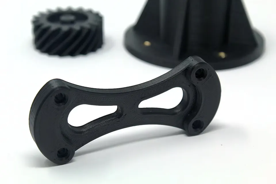
If you want to get started without extensive testing, use this starting profile for a typical functional part made from PETG or high-quality PLA:
| Settings | Recommendation |
|---|---|
| Material | PETG for toughness, PLA for rigidity and precision, ASA/ABS for higher temperatures |
| Orientation | Direct the main tension and bending along the layers, not across them |
| Walls | 3-5 perimeters with a 0.4 mm nozzle |
| Top and bottom layers | 5-7 layers depending on the layer height and part size |
| Infill | 20-35 % for most functional parts, 40-60 % for heavily loaded parts |
| Infill pattern | Gyroid for universal loading, grid or triangles for stiffer technical parts |
| Layer height | 0.16-0.24 mm with a 0.4 mm nozzle |
| Temperature | Preferably the upper part of the filament's recommended range, after verifying that there is no excessive oozing |
| Cooling | Less fan cooling for PETG, ASA, ABS, and nylon; a sensible compromise for PLA |
Treat this as a starting point, not dogma. For a critical part, print a short test in the same orientation and try to break it by hand, load it with a screw, or measure its deflection. A small test often saves hours of printing and a ruined final part.
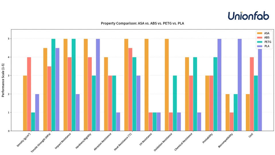
PLA has high rigidity and often very good tensile strength. It is excellent for precise parts, templates, room-temperature brackets, and prototypes. Its weaknesses are brittleness and low temperature resistance. A bracket in a car, a cover near an engine, or a part exposed to sunlight can deform when made from PLA, even if it was very strong at room temperature.
PETG is usually a better choice for practical parts that need to withstand impacts, ing, or outdoor conditions. It is not as rigid as PLA, but it is less prone to brittle fracture and typically has good interlayer bonding. Typical examples include a handle, clip, machine cover, spacer, or part that may occasionally fall to the ground.
ABS and ASA make sense where higher temperature resistance and toughness are important. ASA is also more suitable for outdoor use thanks to its better UV resistance. However, expect to need an enclosed printer, the correct chamber temperature, or at least protection from drafts. A poorly printed ABS part with cracks between the layers will not be stronger simply because the material looks better in a table.
Nylon, polycarbonate, and composite filaments can be very durable, but they are more demanding. Nylon must be dry; otherwise, it loses surface quality as well as mechanical performance. Carbon-fiber materials tend to be rigid and dimensionally stable, but they are not automatically tougher in every direction. Use a hardened nozzle with abrasive filaments.
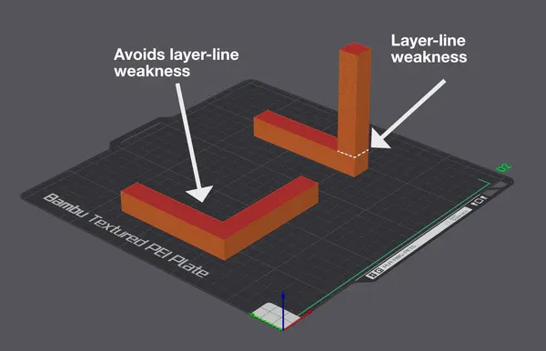
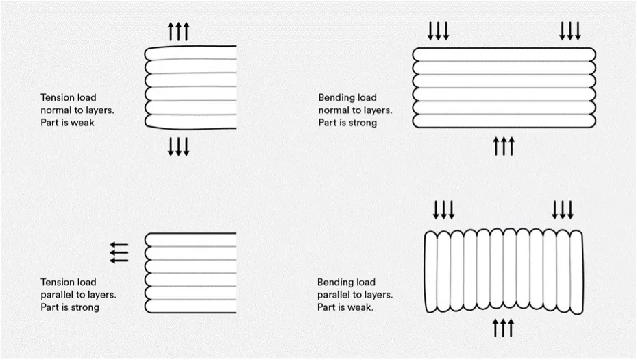
Orientation is often more important than infill. Before slicing, ask yourself a simple question: where will the part try to crack?
Imagine a hook for hanging a cable. If you print it upright, the layers will lie like horizontal slices across the hook's neck. The load then pulls the layers apart, and the hook may crack cleanly along a layer. If you lay the same hook down so that the pulling direction runs along the extruded lines, you take advantage of the strength of the continuous plastic path.
An L-shaped bracket has a similar problem at the corner. If the corner opens across the layers under load, the risk of delamination increases. Rotating the part, adding a larger radius at the corner, using ribs, adding more walls, or splitting the model into two parts that are screwed together after printing in a more favorable orientation can help.
For screw holes, consider whether the screw will pull the layers apart. For repeated screwing and unscrewing, heat-set threaded inserts, a larger wall diameter around the hole, and sufficient material between the hole and the edge of the part are suitable.
Beginners often increase infill from 20 % to 80 % and expect a dramatically stronger part. In reality, for many shapes the outer shell carries much of the bending and impact load. Therefore, adding perimeters is often more effective than using extreme infill.
With a 0.4 mm nozzle, 2 walls mean approximately 0.8 mm of plastic around the perimeter. Three walls provide about 1.2 mm, four around 1.6 mm, and five around 2.0 mm. With a bracket that bends, you will often feel a greater difference between 2 and 4 walls than between 20 % and 40 % infill.
Practical rule:
Do not forget the top and bottom layers. A thin top surface over sparse infill can sag, crack, or feel soft. At a layer height of 0.2 mm, 5-7 top layers are a good starting point for functional parts.
Infill supports the top layers, connects the walls, and helps distribute the load inside the part. However, it is not always efficient to print an almost solid block of plastic. Higher infill increases weight, print time, material consumption, and, with some materials, internal stress.
As a guide:
| Use | Infill |
|---|---|
| Visual models, caps, lightweight parts | 5-15 % |
| Ordinary brackets, boxes, fixtures | 15-30 % |
| Loaded functional parts | 30-45 % |
| Parts with highly localized loads | 45-60 % or local reinforcement |
| Special cases | 80-100 %, only when you know why |
Solid infill is not automatically the best option. In a large part, it can cause stress, warping, and long print times. It is often better to add walls, change the orientation, increase the critical cross-section, or use a local infill modifier only around a screw, pin, or impact area.
Gyroid is an excellent universal choice. It distributes loads in multiple directions, has no rigid intersections of lines in a single layer, and works well for parts where you do not know exactly where the force will come from. It is suitable for covers, brackets, ergonomic parts, and general functional prints.
Grid and triangles provide a stiffer internal structure and can work well in bending for technical parts. A disadvantage can be material accumulation at intersections and a greater risk of nozzle rubbing if the printer or filament is not properly tuned.
Cubic and adaptive cubic are good for larger volumetric parts where you want solid support without unnecessary consumption. Adaptive cubic can save material inside large models and make the structure denser closer to the walls.
Rectilinear is fast and simple. It is sufficient for prototypes and ordinary parts, but for loaded components you will usually choose gyroid, grid, triangles, or a locally reinforced structure.
Layer height affects detail, print time, and interlayer bonding. A lower layer means a finer surface and often better contact between the lines, but printing takes longer and the difference in strength is not unlimited. A layer that is too high can worsen the pressing of material into the previous layer and reduce cohesion.
With a 0.4 mm nozzle, it is practical to stay approximately within the range of 0.16-0.24 mm. For precise and attractive functional parts, try 0.16 or 0.20 mm. For larger brackets where a rougher surface is acceptable, 0.24 mm can be a sensible compromise. If you go to 0.28 mm or higher, verify the strength with a test and monitor layer quality.
Extrusion width is often underestimated. A line that is slightly wider than the nozzle diameter can improve the bonding between adjacent lines. With a 0.4 mm nozzle, a width of 0.42-0.48 mm is common; for strong parts, you can try slightly more after calibration. For large strong parts, a larger nozzle, such as 0.6 mm, may be even more effective. Thicker lines create more robust walls in less time.
Interlayer strength depends on how well the new plastic path bonds to the previous one. A temperature that is too low, a speed that is too high, or cooling that is too strong can cause the layers to separate under load even though they look correct.
For functional parts, generally print toward the upper part of the filament's recommended temperature range. This does not mean printing as hot as possible at any cost. The goal is better interlayer bonding without excessive stringing, deformation, oozing, or loss of detail.
Set cooling according to the material. PLA needs a fan, but for strength-oriented parts it may not always be necessary to cool at maximum. PETG often tolerates less fan cooling, while ASA and ABS usually require limited cooling and a stable warm environment. Nylon, PC, and other technical materials require dry filament and stable conditions even more.
You can recognize wet filament by popping sounds, bubbles, a fuzzy surface, weaker layers, and unstable extrusion. For PETG and nylon, drying before printing is one of the best investments in strength.
A strong part starts in CAD. Sharp internal corners concentrate stress and crack sooner. Add radii, ribs, larger cross-sections at the neck, and sufficient material around holes. If the part has to carry a screw, do not place the hole too close to the edge. If the part has to , design the ible section to be longer and smoother, not as a thin, sharp tab.
With large brackets, it is often better to add ribs than to increase the entire infill volume. A rib placed exactly where bending occurs adds strength precisely and without unnecessary weight. For repeatedly loaded parts, increasing radii and removing notches where a crack could start also helps.
For threads, use threaded inserts, through-bolts with nuts, or a larger plastic thread according to the load. A small self-tapping screw in a thin wall may work for a cover, but not for a part that is frequently disassembled.
Choose PETG, 4 walls, 25-35 % gyroid, a layer height of 0.2 mm, and an orientation that prevents bending from pulling the layers apart. Surround screw holes with sufficient wall thickness and add a fillet where the arm transitions into the base.
Use PLA, PETG, or ASA depending on the ambient temperature. 2-3 walls and 10-20 % infill are sufficient because a cover usually does not carry heavy loads. Strength is improved mainly by screw posts, radii, and sufficient thickness around the threads.
Start with PETG, ASA, nylon, or PC depending on the temperature and chemistry of the environment. Use 5-6 walls, 35-50 % infill, and a larger nozzle if rougher detail is acceptable. Reinforce critical areas around pins, screws, and edges with geometry, not just infill.
PLA will be precise, but it may fail brittlely. PETG or nylon will usually withstand bending better. Orient the part so that the layers do not lie across the thinnest section like the pages of a book. Add a radius at the lever root and avoid a sharp notch.
For a strong FDM print, do not look for one universal infill percentage. First address the orientation and direction of the layers, then the material, walls, and geometry. Infill is important, but for many parts it is not the primary load-bearing element. A sensible starting point for a functional part is 3-5 walls, 20-40 % suitable infill, the correct orientation, good layer adhesion, and a material selected according to the actual application.
When a part really needs to withstand something, treat FDM printing as an engineering process, not just as filling a model with plastic. The strongest print is one in which the shape, material, and direction of the layers work together.


