Doprava zdarma od 1 999 Kč
Rýchla expedícia
Overený obchod
Tisíce zákazníkov




Doprava zdarma od 1 999 Kč
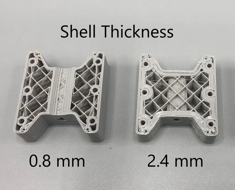
A perimeter is one of the most important settings in a slicer when you want a stronger 3D print. Nevertheless, beginners often overlook it and increase the infill first. However, with typical FDM prints, strength is often highly dependent on the model's walls. Perimeters form the outer shell, maintain the part's shape, protect the infill, and carry a large portion of the load during bending or impact.
The good news is that setting perimeters is not complicated. You only need to understand exactly what you are changing in the slicer, how it relates to the nozzle, and when it makes sense to add another wall instead of increasing the infill percentage.
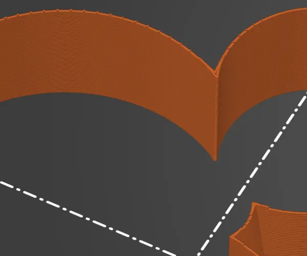
A perimeter is one closed extrusion path around the layer's perimeter. When the slicer cuts the model into layers, it first creates the outer and inner outline lines. These lines are placed next to each other and together form the model's wall.
In different slicers, you may encounter various names:
The principle is the same. If you set 2 perimeters, the slicer prints two adjacent lines of material around the perimeter. If you set 4 perimeters, the wall will be significantly thicker and less space will remain inside for infill.
With a standard 0.4 mm nozzle, the extrusion width is usually approximately 0.4 to 0.45 mm. Three perimeters therefore create a wall roughly 1.2 to 1.35 mm thick. The exact figure depends on the printer profile, material, and line width settings.
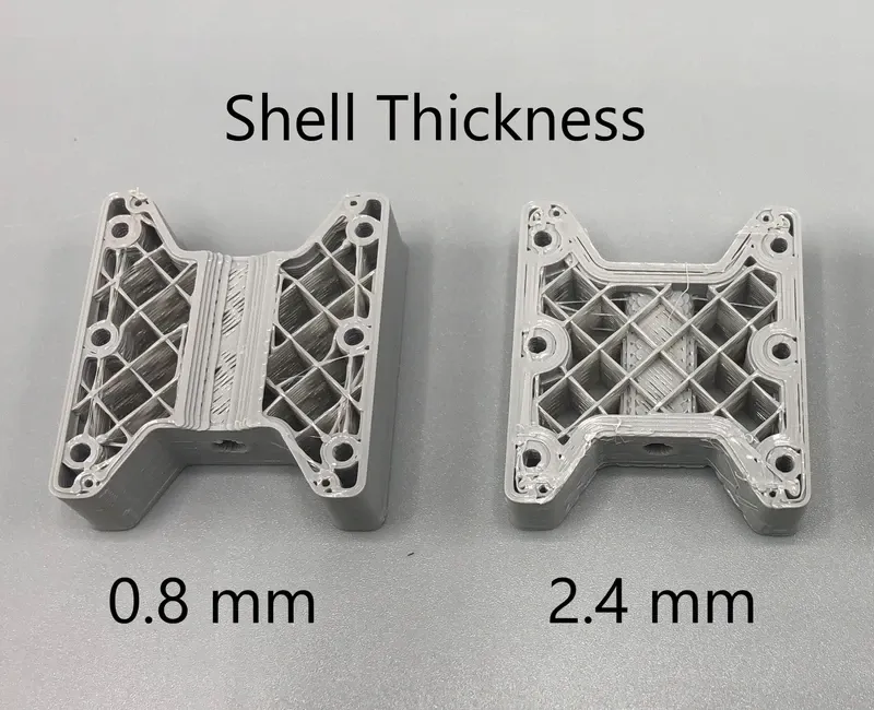
Imagine a hollow tube. Even though it is not solid, it can be very strong because the material is far from the center and resists bending well. Many 3D-printed parts work in a similar way. During bending, twisting, or impact, the model's outer layers do most of the work. The infill helps, but dense infill alone often does not make as much difference as a stronger wall.
That is why a part with 4 perimeters and 25% infill can be more practical than a part with 2 perimeters and 60% infill. It will have stronger edges, better threads, more durable corners, and often a more reasonable print time. At the same time, less material is wasted inside the model, where additional plastic may no longer provide a corresponding improvement.
Perimeters are especially helpful where the part:
Infill is the internal structure of the model. It supports the top layers, reduces deformation, and increases resistance to compression. Perimeters, on the other hand, are a continuous shell around the perimeter. Both settings work together, but they do not solve the same problem.
When a print breaks at a corner or around a screw hole, simply increasing the infill from 20 to 50% often does not help. It is usually better to add a perimeter, increase the radius in the model, rotate the part on the build plate so that the layers are not subjected to delamination, and only then fine-tune the infill.
Conversely, in a large solid part that is compressed or carries pressure across its entire surface, infill density may play a greater role. The practical setting therefore always depends on the direction of the load.
There is no single universal number, but for a standard 0.4 mm nozzle, you can start as follows:
| Model use | Recommended starting point | Note |
|---|---|---|
| Decorations, figurines, appearance prototypes | 2 perimeters | Fast printing, low consumption, strength is not the main goal. |
| Standard practical parts | 3 perimeters | A good starting point for holders, boxes, covers, and household parts. |
| Load-bearing holders, assembly parts, threads | 4 to 5 perimeters | Better edges, stronger holes, and greater resistance during bending. |
| Parts for screws, inserts, and repeated use | 5 to 6 perimeters in critical areas | If the slicer allows it, use local reinforcement only where it is needed. |
| Vases and thin-walled decorations | 1 perimeter or vase mode | Suitable for appearance, not mechanical loads. |
For a PETG wall bracket, I would typically start with 4 perimeters, 25 to 35% infill, and larger corner fillets. For a PLA electronics enclosure, 3 perimeters and 15 to 20% infill are often sufficient. For a small figurine or dimensional test, 2 perimeters are usually enough.
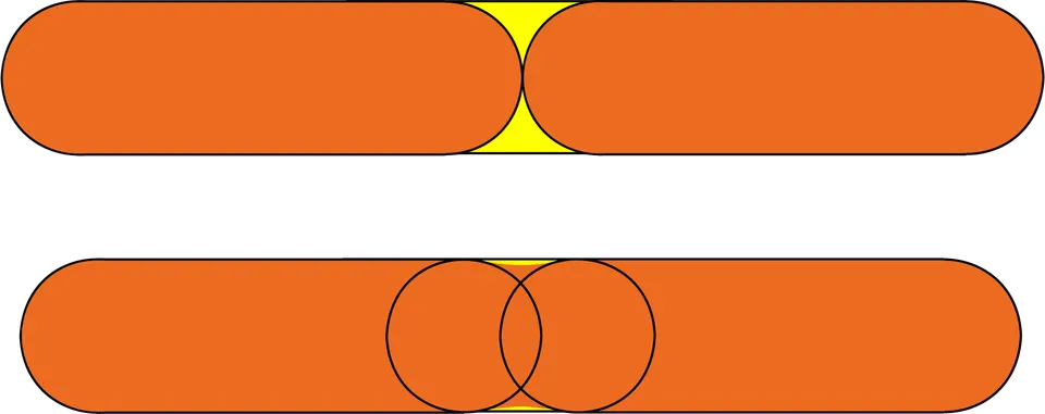
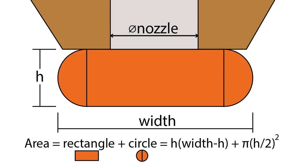
The number of perimeters alone is not enough. Extrusion width is also important. A 0.4 mm nozzle with 3 perimeters produces a different wall than a 0.6 mm nozzle with 3 perimeters. With a larger nozzle, the same number of perimeters can be significantly stronger because each line is wider.
The approximate calculation is simple:
wall thickness = number of perimeters × line width
When printing with a line width of 0.45 mm and setting 4 perimeters, the wall will be approximately 1.8 mm thick. If the model contains a wall only 1 mm thick, four perimeters will not physically fit into it. The slicer will then use fewer lines, adjust the extrusion width, or create a compromise according to its algorithm.
For functional parts, it is therefore a good idea to consider perimeters as early as the model design stage. If you want 4 lines with a width of 0.45 mm, design the wall to be at least around 1.8 mm thick. For 5 lines, allow approximately 2.25 mm.
Adding a perimeter makes sense when edges, holes, hooks, thin walls, or corners are cracking. It also helps when the infill pattern is visible on the surface, when the part warps around a screw hole, or when you need better watertightness.
Increasing the infill makes sense when the part gets dented, top surfaces sag, the model is large and hollow, or when you need better resistance to compression. For most standard parts, it is reasonable to set 3 to 4 perimeters first and then increase the infill only as needed.
A common mistake is printing everything with 100% infill. Such a print takes a long time, is expensive, may warp more, and is not automatically the most reliable. A solid part also tolerates over-extrusion, poor cooling, or internal material stress less effectively.
Perimeters are not a miracle if the part is poorly oriented. FDM prints are usually weakest between layers because the layers bond to each other but are not made from one continuous piece of material. If you print a bracket so that the load pulls it apart along the layers, it may crack even with a high number of perimeters.
With a hook, bracket, or lever, always ask yourself: will the force pull the layers apart, or will it act mainly along the lines? If possible, rotate the model so that the main tension and bending run as much as possible along continuous material strands. Add fillets to sharp corners, because that is often where a crack begins.
Start by determining where the model will be subjected to loads. For a holder, this is usually the area around the screws and the transition between the base and the arm. For a box, these are the hinges, clips, and corners. For a gear or lever, the critical areas are around the axle and teeth.
Then set up the slicer as follows:
Local reinforcement is often the best approach. Instead of printing the entire part with 6 perimeters, you can add material only around holes, mounting points, and hooks. Some slicers support modifiers that set a different number of walls or infill only in a selected area.
A perimeter is an outline line that forms the wall of a 3D print. More perimeters mean a thicker shell, stronger edges, and often a better balance between strength, weight, and print time. For standard parts, start with 3 perimeters; for functional and load-bearing parts, use 4 to 5 and increase the infill only according to the specific load.
The best result, however, does not come from a single number in the slicer. Model strength is affected by a combination of perimeters, infill, material, temperature, layer bonding, orientation on the build plate, and the part's design itself. If you want a stronger print, do not fill the model with plastic blindly. Reinforce the walls and critical areas first, then fine-tune the rest.


